

IMAGE CAPTURE FOR RECONSTRUCTION
Choose image detail and coverage before starting Terra processing
DJI Terra GSD questions usually begin in the field: how high should the drone fly, how much overlap is enough, and how detailed will the model be? Those choices affect the input imagery long before the reconstruction starts.
This guide explains ground sample distance, camera footprint, flight-height changes, front and side overlap and motion blur. It includes simplified calculations to make the tradeoffs clear, while keeping resolution separate from demonstrated survey accuracy.
What is GSD in drone mapping?
Ground sample distance describes the ground spacing represented by neighboring image pixels under the applicable viewing geometry. A nominal GSD of 2 cm/pixel means approximately 2 cm between pixel centers on the assumed target surface.
DJI’s GSD introduction explains how camera parameters and flight height influence this value. For an approximately nadir view of level ground, flying higher with the same camera normally increases GSD and the area covered by each image.
A smaller GSD can help resolve finer visible features. It also tends to increase the number of images required to cover the same area at the same overlap. Choose it around the deliverable rather than simply seeking the smallest number.
GSD is not a survey accuracy certificate
A 2 cm/pixel image does not prove that every reconstructed coordinate is accurate to 2 cm. Positioning, camera behavior, geometry, control, image quality and independent checks all matter.
A simple GSD and flight-height calculation
For a nadir image over a level target, an approximate relationship in one image direction is GSD = H × S ÷ (f × P). H is camera height above the target, S is physical sensor size in that direction, f is actual focal length and P is the corresponding image dimension in pixels.
- Use consistent length units for sensor size and focal length.
- Use height above the imaged target, not an unexplained controller altitude value.
- Use the actual lens focal length, not a 35 mm-equivalent value.
- Calculate both image directions where needed and check the appropriate planning model.
Illustrative example, not a DJI camera recommendation
Assume H = 80 m, S = 13.2 mm, f = 8.8 mm and P = 5,472 pixels. The approximate GSD is 0.0219 m/pixel, or 2.19 cm/pixel. At 120 m above the same level target, it becomes approximately 3.29 cm/pixel.
These are example inputs for explaining the equation. They are not a mission prescription or a stated performance result for a particular aircraft. Lens geometry, oblique views and real terrain require a suitable platform-specific plan.
To estimate height for a target GSD, rearrange the relationship to H = GSD × f × P ÷ S. Review the result against permitted operating conditions and the capture system’s capabilities.
Why height above takeoff can mislead a mapping plan
A flight altitude measured relative to takeoff is different from height above the photographed ground. If the terrain rises or falls while the aircraft follows a constant takeoff-relative level, the camera-to-target distance changes.
For an illustrative flight 100 m above takeoff, ground that rises 30 m leaves an approximate camera-to-ground separation of 70 m. Ground that falls 20 m leaves approximately 120 m. The nominal resolution and coverage change accordingly.
Buildings and piles introduce the same issue: roof or pile-top distance differs from surrounding ground distance. Check the surface that must be resolved, not only the site’s lowest point.
Supported terrain-following functions can help manage variable terrain, but mode availability and sensing or model requirements depend on the aircraft and firmware. DJI’s geospatial FAQ provides examples; use the current platform manual for the actual mission.
Terrain models and obstacle clearance are different inputs
A terrain-following plan needs appropriate elevation information and an assessed flight environment. A coarse terrain model does not establish the location of every tree, wire or newly built structure.
Front overlap and side overlap: what the percentages mean
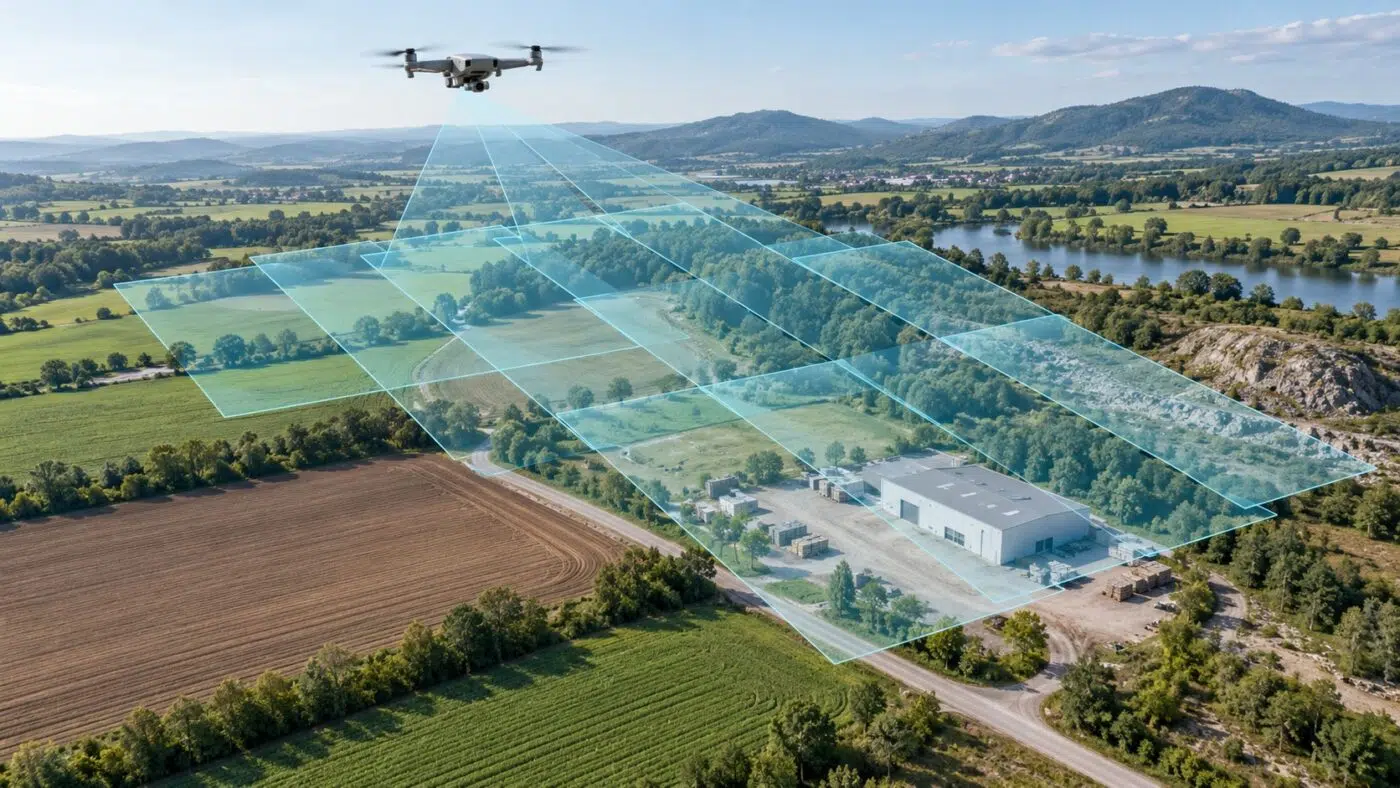
Front overlap is the shared coverage between successive photographs along a flight strip. Side overlap is the shared coverage between neighboring strips. Both help the reconstruction find common scene information across images.
DJI has published visible-light mapping workflows using 80% front overlap and 70% side overlap. These are documented examples, not universal settings for every sensor, object or reconstruction. See the Matrice 4 Enterprise mapping comparison.
Check scene texture, relief, intended 3D coverage and the selected capture mode. Repeating crops, reflective surfaces or strongly varying terrain may not provide useful matches simply because a nominal percentage was entered.
Camera-footprint example
If the footprint length along the flight direction is 100 m, 80% front overlap corresponds to approximately 20 m between exposures. If the footprint width is 150 m, 70% side overlap corresponds to approximately 45 m between strips.
At 10 m/s, 20 m between exposures requires an interval of approximately 2 seconds. These simplified values assume level terrain and consistent geometry; check actual camera timing and the mission planner.
Image sharpness can defeat a small nominal GSD
A fine pixel footprint is useful only when the image contains usable detail. Motion blur, incorrect focus, unsuitable exposure, compression or rolling-shutter effects can reduce practical reconstruction quality.
A simplified motion-blur example
At a ground-relative speed of 10 m/s and an exposure of 1/1,000 second, the aircraft travels 0.01 m during exposure. At 2 cm/pixel, that is approximately half a pixel of translational movement. At 1/250 second, the distance is 0.04 m, or approximately two pixels.
This simplified estimate does not include attitude change, vibration, lens effects or shutter readout. Use it to understand the speed/exposure tradeoff, then review actual captured photographs.
- Inspect fine detail at full image resolution before the full mission.
- Check focus on the relevant target rather than only nearby objects.
- Review highlights, shadows and exposure consistency.
- Match flight speed to camera timing and scene conditions.
- Preserve original image files and metadata for reconstruction.
Processing can address some supported camera effects, but it cannot guarantee recovery of missing detail. Our Terra reconstruction troubleshooting guide covers downstream investigation.
Nadir and oblique imagery solve different coverage problems
A nadir image looks approximately downward and is useful for plan-view coverage. Oblique imagery observes objects from an angle and can improve coverage of façades, steep slopes and complex structures when planned appropriately.
A single ground GSD value does not fully describe an oblique scene: distance and pixel footprint vary across the image. Review the particular surfaces needed for the deliverable and whether they are visible from enough viewpoints.
| Need | Coverage to review |
|---|---|
| Orthomosaic overview | Consistent plan coverage, edges and image quality. |
| Building or infrastructure mesh | Vertical surfaces, occlusion and suitable viewing angles. |
| Stockpile geometry | The pile toe, slopes, peak and reference evidence. |
| Thermal reconstruction | Compatible paired capture and the thermal camera’s relevant resolution. |
Read our stockpile measurement guide for the quantity workflow, and thermal mapping guide for the separate paired RGB/infrared capture requirements.
For a supported compact mapping aircraft, see the Matrice 4E guide and confirm the selected mode against its current documentation.
Capture GSD, output resolution and processing load
The image GSD describes the capture. An orthomosaic pixel size or elevation-grid spacing is an output choice. They are related decisions, but resampling an output to smaller pixels does not add observed detail to the original photographs.
For a simplified large-area, same-camera nadir plan at unchanged overlap, halving camera height reduces each image footprint’s area to about one quarter. Covering the same area can therefore require roughly four times as many images, before boundary and mission effects.
Likewise, increasing overlap increases the capture count and processing load. The benefit should be assessed against the actual matching and coverage need, not against image count alone.
Before committing to a large dataset, check the Terra workstation requirements and test a representative capture. Keep adequate data storage and a repeatable folder structure.
DJI Terra processes the acquired data. Plan current Enterprise mapping missions in the supported flight application and check version-specific exceptions rather than following old Terra flight-planning screenshots.
A practical capture checklist before Terra reconstruction
- Define the deliverable and the smallest relevant feature to be observed.
- Choose the supported camera, lens and capture mode.
- Set a target resolution and review height above the actual target surfaces.
- Plan front and side coverage, including site boundaries and difficult objects.
- Check speed, interval, focus and exposure against representative images.
- Agree positioning, control and independent validation.
- Inspect the capture before leaving the site, then archive the original files.
- Test reconstruction quality before scaling the same method to a larger survey.
Our supported drones and sensors guide helps with compatibility. Use the accuracy, GCP and RTK guide to plan acceptance checks independently of the nominal GSD.
Keep the mission settings and observed conditions with the processing records. For repeat surveys, document deliberate changes in height, overlap or camera setup so differences in the results can be explained.
DJI Terra GSD and image overlap FAQ
Does 1 cm GSD guarantee 1 cm survey accuracy?
No. GSD describes image sampling. Demonstrated positional performance requires appropriate acquisition, positioning, control and independent checks.
What overlap should I use for DJI Terra?
Use a scene- and platform-appropriate plan. DJI’s published visible-light examples include 80% front and 70% side overlap, but another sensor or difficult object can require a different method.
Can I improve capture detail by choosing a smaller output pixel size?
A smaller output pixel can change sampling or presentation. It does not recover detail that the original capture failed to observe.
Is the controller’s altitude the same as height above the target?
Not always. Understand whether the displayed value is relative to takeoff, a sea-level reference or a supported terrain-following setup, and assess the actual target distance.
Is more overlap always better?
It can improve shared coverage, but also increases mission duration, file count and processing load. Evaluate whether the added images improve the reconstruction evidence for the intended result.
Match your capture plan with the Terra processing workflow
Tell us your aircraft, camera, site type and required outputs. We can help you assess Terra compatibility and licensing for the reconstruction stage, with practical guidance on preparing suitable inputs.
Official documentation
- DJI explanation of ground sample distance
- DJI visible-light mapping comparison and overlap example
- DJI capture, camera and terrain-following guidance
- DJI photogrammetry accuracy white paper
- DJI Terra version-specific preparation and workflow FAQ
Independent guide by Drone Emotions. Documentation reviewed on 12 October 2026. Consult the documentation for the installed software and capture-system releases.


