

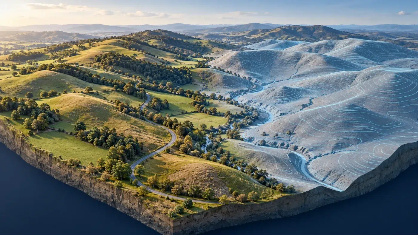
ELEVATION DATA TO TOPOGRAPHIC DELIVERABLES
Build contour maps from the right elevation surface
DJI Terra contour lines are useful when a project needs a readable representation of terrain levels. The important first decision is the source surface: contours generated from roofs and vegetation describe different geometry from contours derived from ground observations.
This guide explains DEM, DSM and DTM terminology, ground classification, interval selection and validation. It then provides a documented Terra elevation-raster → QGIS contour workflow that can be checked before GIS or CAD delivery.
What contour lines show, and what they do not
A contour connects locations with the same elevation on the source surface. Its shape depends on that surface, the chosen elevation interval and the extraction method. Contours summarize height geometry; they do not independently validate a survey.
Use them for topographic context, terrain review and agreed planning deliverables. Preserve the underlying elevation data when the recipient needs to inspect values or perform further analysis.
A smaller interval does not create a more accurate survey
Generating lines every 0.10 m instead of every 1 m adds more levels to the display. It does not reduce the vertical uncertainty of the source, recover hidden terrain or establish engineering suitability.
DEM, DSM and DTM: identify the actual terrain input
Terminology varies between software and project specifications. Describe what the dataset represents and how it was generated instead of relying only on its acronym.
| Term | Practical interpretation | Contour consequence |
|---|---|---|
| DSM | An elevation surface that can include trees, roofs and other observed objects. | Contours may follow above-ground features. |
| Ground-based DEM | An elevation raster generated from observations treated as ground. | Useful for terrain contours if coverage and classification are suitable. |
| DTM | A terrain-model deliverable whose exact definition depends on the specification. | Confirm whether ground filtering, breaklines or additional surveyed features are required. |
| TIN | A triangulated representation of selected elevations. | Triangle geometry and breaklines affect the resulting contours. |
For context on the available Terra products, see our reconstruction outputs guide. This article focuses on creating and reviewing contours, rather than listing every export format.
Why ground classification matters for contour generation
DJI documents ground-point classification and DEM output for Zenmuse L2 data processed in Terra. Its earlier Terra ground classification and DEM announcement also explains the role of separating ground observations from surface objects.
Review classified ground points in representative areas before generating a terrain raster. Examine slopes, vegetation transitions, drainage features, buildings and sparse-coverage areas. Classification can misidentify observed points; it cannot measure a surface that was never captured.
- Dense vegetation can reduce available ground observations.
- Roofs, vehicles and low objects may contaminate an automatic ground class.
- Ditches and steep embankments may be simplified or incorrectly excluded.
- Noise below the terrain can introduce artificial depressions.
- Interpolation can fill a gap without adding new measurement evidence.
Use our Terra and Zenmuse L2 workflow for the acquisition context. Where additional point-cloud editing is required, review the relevant tools and separate licensing through the Terra vs DJI Modify guide.
Do not assume an RGB photogrammetric surface provides measured ground beneath vegetation. Match the capture method and supplementary survey plan to the terrain evidence required.
Prepare a suitable elevation raster from Terra
Select the supported terrain or elevation output for the processing task. DJI documents GeoTIFF DEM generation from ground point-cloud data. Retain the original cloud and report with the raster so the ground selection remains traceable.
- Confirm the required horizontal reference, height reference and units.
- Review the ground selection and its coverage before accepting the derived elevation model.
- Choose a raster resolution suitable for the observations and intended terrain detail.
- Inspect the resulting elevations, edges and NoData areas.
- Compare independent check observations with the derived surface.
- Save a reviewed raster revision for contour extraction.
Exporting a very small raster cell does not automatically create observations at that spacing. The useful resolution depends on source coverage, terrain shape and interpolation.
If heights appear inconsistent with the project benchmarks, consult our coordinate systems and geoid guide. Our quality report guide helps separate processing indicators from independent validation.
Choose a contour interval that matches the purpose
Agree the interval with the recipient and the relevant project specification. Consider vertical performance, terrain variation, map scale and readability. Avoid treating one interval as correct for every drone survey.
| Example | Possible display interval | Decision to check |
|---|---|---|
| Broad site overview | 2 m or 5 m | Does it communicate the terrain without hiding important relief? |
| More detailed terrain presentation | 0.5 m or 1 m | Does the validated source support the intended interpretation? |
| Small, nearly flat site | A tighter interval only if justified | Will noise or uncertainty dominate the apparent relief? |
| Required engineering deliverable | As specified by the project | What evidence and additional surveyed detail are needed? |
An illustrative site spanning 100 m to 120 m in elevation has many more contour levels at 0.5 m spacing than at 2 m spacing. That changes visual density, not the quality of the underlying observations.
The interval uses the elevation raster’s units. Entering 1 into a raster expressed in feet means one foot, not one metre. Record the unit next to the interval in the report.
Extract contour lines from a Terra elevation raster in QGIS
The documented route here uses an accepted elevation raster from Terra as the input to QGIS. It avoids assuming that every Terra sensor, edition or reconstruction task provides the same direct contour export.
QGIS documents a GDAL Contour algorithm under Raster → Extraction and in the Processing Toolbox. The QGIS 3.44 extraction documentation describes its parameters.
- Load the elevation raster and review the CRS, band, numeric values and units.
- Open Contour and choose the elevation input and band.
- Set the agreed interval and the elevation attribute field.
- Review the offset if the required levels use a specified base.
- Choose the 3D-vector option only where the handover requires vertex elevations.
- Keep appropriate NoData handling and save the output to a permanent file.
- Run the extraction, then inspect line geometry and elevation values.
Our Terra to QGIS guide covers loading the GeoTIFF and preparing the GIS project. Here, the additional task is to create and validate the contour layer.
Do not contour an orthomosaic by mistake
An RGB orthomosaic stores image information. The contour algorithm requires numeric elevation data. A colorful picture of terrain is not necessarily an elevation raster.
Review spikes, loops, gaps and terrain discontinuities
Inspect the lines alongside the source elevation raster and a hillshade or other useful terrain display. Use recognizable site features and independent observations to investigate suspicious patterns.
- Small isolated loops can represent real terrain or noise; inspect their source.
- Lines around roof shapes may indicate above-ground objects in the input.
- Straight bridges across gaps can reveal interpolation or boundary effects.
- Terraces or strip patterns may arise from source or processing inconsistencies.
- NoData edges can terminate lines and should remain identifiable.
- Very dense lines may be appropriate on steep slopes, but can also make the map unreadable.
When a pattern is wrong, correct the relevant input or method and regenerate a documented revision. Avoid hiding a terrain error with cosmetic smoothing.
Smoothing is a presentation or modeling decision
Smoothing can change where a contour lies. Preserve the original extraction, explain any adjustment and assess its effect on the intended use. A clean-looking line is not evidence of a more faithful terrain model.
Deliver contours to GIS or CAD without losing elevation meaning
Agree whether the recipient needs 2D lines with an elevation attribute, 3D lines with vertex elevations, or a terrain surface as well. These deliverables are not interchangeable.
| Deliverable | What to confirm |
|---|---|
| GIS vector layer | CRS, elevation attribute, units and accompanying metadata. |
| CAD contour file | Entity type, numeric elevations, units and expected coordinate placement. |
| Terrain surface | Accepted raster or triangulated model, boundaries and required breaklines. |
| Presentation map | Interval, reference, capture date, legend and declared limitations. |
A visible contour label does not prove that the CAD entity has a nonzero Z value. Open the actual exported file in the receiving application and inspect representative lines numerically.
Our Revit workflow guide addresses a different BIM reference handover. For civil design, confirm the surface and contour requirements with the engineering team before choosing the exchange format.
Keep a short terrain and contour methodology note
- Source capture, date and Terra processing revision.
- Ground-selection method and areas with limited coverage.
- Elevation model type, raster resolution and interpolation approach.
- Horizontal and height references, plus units.
- Contour interval, base offset and extraction software release.
- 2D or 3D output definition and elevation attribute.
- Validation evidence, smoothing or manual edits and intended-use limits.
Keep the raster used for extraction alongside the delivered contours. For repeat surveys, use a consistent method and explain changes in source coverage, classification or processing before interpreting new line positions.
DJI Terra contour lines FAQ
Can I create contour lines from DJI Terra outputs?
Yes, suitable elevation outputs can feed a contour-generation workflow. This guide uses a reviewed Terra elevation raster and QGIS extraction. Check direct Terra export availability separately for the actual processing task and release.
Should I use a DSM or a ground DEM?
Choose the surface specified by the project. For bare-earth terrain contours, review ground observations and classification; a DSM can include buildings and vegetation.
Is a 0.10 m contour interval proof of 0.10 m accuracy?
No. Interval controls which levels are drawn. Survey performance needs appropriate independent validation of the source and derived model.
Can classification reveal ground hidden under a roof?
Classification labels observed data. It cannot produce a measured floor or ground surface where no suitable observations exist.
Do I need DJI Modify for every contour workflow?
Not necessarily. Choose tools around the required ground editing and terrain products. Confirm feature availability and licensing for the specific data and releases, rather than assuming an additional product is always required.
Prepare Terra data for the terrain deliverable you need
Tell us the sensor, site conditions and requested elevation products. We can help identify the Terra processing and licensing requirements before you commit to the reconstruction workflow.
Official documentation
- DJI Zenmuse L2 ground classification and DEM outputs
- DJI explanation of ground-point DEM generation
- DJI Modify point-cloud editing overview
- QGIS 3.44 contour extraction parameters
- DJI Terra manuals and release documentation
Independent guide by Drone Emotions. Documentation reviewed on 12 October 2026. Consult the documentation for the installed software and capture-system releases.


